
Green Building Advisor - Concrete-Free Slab: Foundation-to-Wall Connection
July 13, 2022, by Josh Salinger
At my firm, Birdsmouth Design-Build in Portland, OR, builders and architects ask regularly if we can help them design high-performance assemblies that are well-above code, approachable for the average builder, and cost-effective for clients. The question seems eminently solvable, but on further inspection can prove tricky. Expanding this question to cover most climate zones in North America makes things even fuzzier. When GBA approached me to share a couple of our go-to details for the Expert Exchange program, my mind went straight to this conundrum. How do we share details that can be useful to broad swaths of people when there are so many variables to consider beyond climate zone including budget, availability of materials, and local trade knowledge, to name a few?
One thing that remains consistent no matter the conditions is the importance of getting the four control layers right. All our assemblies integrate strategies to control bulk water, air movement, vapor drive, and thermal losses—in that order.
For the purposes of this article—part one of two—I will assume most readers are fairly versed in controlling bulk water. I’ll jump to the next layer in line of importance: the air barrier. In most homes, the leakiest parts of the building are the top plate-to-roof connection followed by the bottom plate-to-foundation connection. Focusing on these two areas seems beneficial to the greatest number of people. I will share how our firm approached the detailing of these two locations on a new home we are building in Damascus, OR, climate zone 4C. Here, I will address the foundation-to-wall connection. In my next post, I will talk about the wall-to-roof connection.
A little backstory
Both assemblies are taken from a certified Passive House build. When designing and building to best practices, our firm uses the Phius 2021 standards. (We have found it to be a shoo-in rather than an aspirational challenge.) We designed these assemblies to cost-effectively meet the zero-energy objective, and they also happen to meet the Phius standards. Lately, we have noticed less of a divide between well-designed and optimized zero-energy projects and Phius-certified Passive House projects. This may not be the case for every team in every climate zone, but it is what our team has found. I hope to illustrate that the detailing of high-performance homes can be relatively straightforward using familiar methods and materials with just a few key adjustments to one’s standard practices.
Transition from foundation to wall
Our foundation-to-wall connection relies on the concrete-free slab-on-grade assembly that we have been using lately. (Previously, we were pairing the floating plywood slab with ICF construction, but GBA Expert Member Malcom Taylor pointed out that we could create a knockout at the inside top of a typical stem wall and insulate it with rigid foam. This allows us to skip both the ICFs and the exterior insulation on the stem wall.) By cutting out the concrete and replacing it with wood—R-value of about 1 per in.—and insulating it from the concrete stem wall, we could thermally break the assembly enough to skip the exterior insulation at the stem wall and avoid large energy losses; it also mitigates potential for condensation in this location. We even ran a THERM model to prove it (below). This approach allows for more typical construction and removes steps required with ICFs and exterior stem wall insulation, such as installing foundation protection board or stucco.
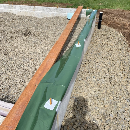
With the exception of the 5-1/2-in. knockout that we created by setting a 2×6 on the inside top of the form before pouring the concrete, the stem wall and footing are typical. After placing our 3/4-in. gravel with no fines to the interior of the foundation for our capillary break and soil gas depressurization field, we set a 4-in. perforated foundation pipe and a 4-in. ABS pipe to the exterior of the footing that carries water from the downspouts via crushed rock wrapped in filter fabric. Both pipes drain to daylight and these, along with the 3/4-in. rock on the interior create the bulk water control strategy for the bottom of the building. We then backfill the foundation on the exterior being sure to slope the grade away from the foundation further directing bulk water from the building—all pretty typical.
Prior to setting the mudsill, we drape a 12-in. strip of 10 mil. polyethylene over the top of the stem wall and detail around the J bolts and hold-downs with a vapor impermeable tape. This extra step takes little time and creates a robust air- and vapor-control layer at the bottom of the building. The flap gets taped to the interior polyethylene membrane just under the plywood to make a continuous air and vapor barrier, which extends under the sill plate to the exterior where we cut it to about 1 in. proud of the wall; it gets flapped down and covered with 4-in. Siga Fentrim tape, connecting the plywood sheathing to both it and the foundation stem wall. Note that we still place a strip of sill seal on top of this strip to protect it when the plates get fastened on and take the weight of the building. It is also a belt-and-suspenders approach to breaking the capillary action of the concrete stem wall to the wood-framed wall.
We shift the bottom plate in a 1/2 in. from the exterior plane of the stem wall. This accomplishes a few things. First, it sets the plywood sheathing to the same plane as the stem wall, which makes taping the air barrier easy. It also minimizes the projection of the siding over the exposed stem wall, which helps when detailing the exterior insulation and rainscreen. Note that it is important to install the sheathing up a minimum of 3/8 in. to stop any capillary wicking from the concrete to the wood.
On the interior, this method planes out the framing with the 1-1/2-in. by 5-1/2-in. Formular NGX rigid insulation that was installed in the recess created by the 2×6 after the form was stripped. By setting the perimeter wall closer to the interior of the home, we are able to more easily cover up the 3/4-in. gap that is needed for the floating plywood to expand and contract with our baseboard and shoe. Also, it allows us to put a 5/8-in. by 3-in. slice of rigid insulation on the interior of the mudsill (in plane with the 5/8-in. sheetrock), which has a substantial impact on the thermal bridging at this location. These are simple differences that don’t add significant time or cost to this part of the assembly and are easy to detail in the field.
Side note: site-fabricated insect screen
Insect screens at the foot of rainscreen systems is something people ask about. We typically use a Cor-A-Vent product, which is a corrugated plastic strip that allows airflow and drainage but stops bugs and critters from getting behind the siding. Here, the house is in a wildfire-prone area, so plastic was ruled out. Plus, we wanted to protect the bottom edge of the 2-1/2-in.-thick wood-fiber insulation from insects and damage. We needed something rigid enough that it would stay straight, but not so thick as to be overly expensive. We wanted stainless steel to avoid galvanic reactions, and we know it to be a material that will last the life of the building. We landed on a woven-wire cloth, specifically 48-in. by 100-in. sheets of 20 Mesh GPI Woven Stainless Steel Cloth at .016 ga. We cut it into 10-in.-wide strips and with a metal brake bent it on-site into the correct shape and dimensions. If we could have gotten away with just 8-in.-wide strips, it would have been roughly the same cost as the Cor-A-Vent, but at 10 in. it was more expensive. Being in wildfire country made it necessary and this solution proved easy to install and super effective.
I’ll pick up in the next post with detailing the 2×6 wall before explaining how we transition to the roof system.
_________________________________________________________________________
Josh Salinger is founder and CEO of Birdsmouth Design-Build. Images courtesy of the author.