
Green Building Advisor - Detailing a Wall-to-Roof Truss Transition
August 09, 2022, by Josh Salinger
Starting with the wall
The wall itself is a 2×6 stud wall with intermediate framing with studs at 24 in. o.c. We sheath the wall with 1/2-in. CDX plywood with the seams taped using Siga Wigluv to continue the air barrier up the wall. The stud bays are insulated with dense-packed cellulose, blown in and tested to a density of 3-1/2 lb. per sq. in. to prevent any future settling. This makes the CDX plywood the least permeable part of our assembly at approximately 10 perms, therefore making it the vapor control layer. This is the layer we are most concerned about seeing condensation on the coldest stretches of the year and therefore we want to keep it warm enough to keep it safe.
To keep the sheathing warm, on the exterior of the wall we install 1-3/8-in. Steico wood-fiber rigid insulation board. We like this product because of its low embodied carbon and ease of installation with the tongue-and-groove profile that can be installed “off layout,” meaning the seams don’t need to line up with the studs to install it. Because this is a wood product being installed in a climate that sees 42 inches of rain on average per year, we install a mechanically attached water-resistive barrier (WRB) to the outside of the wood-fiber board to complete our bulk water control layer.
Adding a WRB
Even though this insulation is commonly used in Europe without protection of a WRB (and even spec’d from the manufacturer to be used as such) it is still a wood product that will see bulk water and we mitigate any risk by moving the WRB to this plane (whether one believes there is risk or not, by doing this we remove the discussion from the table). It’s not a difficult step and the costs of the tapes combined with the WRB are about equal to the cost of a similar self-adhered or liquid-applied product. We then install1/2-in. plywood battens to create a rainscreen gap and then attach the cladding.
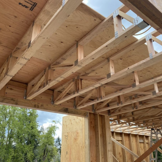
Integrating a service cavity
On the top side of this assembly, we create a space within the thermal and air control layers to strategically locate our mechanical, electrical, and plumbing (MEP) systems. We do this by hanging 14-in. parallel chord trusses (PCTs) that we have designed in tandem with our HVAC ducting strategy to have space to distribute the conditioned air. Once the PCTs are hung we simply sheath the topside with plywood, tape the seams and tape them down and over onto the wall sheathing with Siga Wigluv to complete a simple, continuous, and durable air control layer.
Benefits of a plywood air barrier
This plywood “deck” also gives the carpenters a safe place to stand and work while setting the raised-heel roof trusses that will land directly on top of it, making the work efficient. Something to note is the need to protect the tape when walking on the deck and scotching the trusses around, especially when it’s raining or if working on a muddy site. In our case, we laid a sheet of Siga Wetguard over the deck prior to setting the trusses. This worked perfectly and kept the plywood air barrier and tapes perfectly intact during the rainy Oregon spring when this was installed.
Materials and methods
We spec truss loc screws in lieu of H2.5 or hurricane ties; this keeps the air barrier simpler and it’s quicker to install. Prior to sheathing the roof trusses, we build baffles out of 2x2s and 1/4-in. plywood, which we nail in-between the top chords of the roof trusses to create a 1-1/2-in. air gap for our fully ventilated roof. Once the roof is sheathed and dried in, we place 14 in. of cellulose insulation on top of the air barrier deck for an R-value of 60; that’s enough to meet the Phius 2021 standard in our climate zone and allow us to offset the energy use to zero with a small roof-mounted solar array.
Although this assembly uses exterior insulation and has a unique plywood slab assembly, it is a fairly straightforward installation. The detailing is effective and it’s easy to hit very low air-leakage target rates. Plus, the assembly is fully free of thermal bridges. Yes, it is more complicated than a code-level assembly, but the materials are all the same and a lot of the methods employed are like conventional construction. It’s possible to substitute different exterior insulation materials, swap PCTs for TJIs, use a foamglass gravel or mineral wool under the slab, change the locations of the WRB or even use a Zip System sheathing. I can also recommend using FSC-certified lumber and low-embodied carbon concrete mixes to further reduce the impact of these assemblies on the climate.
The point is: as long as the four control layers are handled diligently, making substitutions to accommodate specific needs, materials availability limitations, and energy or certification targets is perfectly within reach with this general framework.
A solid framework
Over the past 15 years, we have rarely used the same assembly twice. At our internal meetings, we talk about the desire to use the same assembly for every home, refining it for optimal efficiency. But the reality is that every home we’ve built has had unique inputs or challenges that require tweaking some part of the assembly. For instance, the home we will build next is in a wildfire hazard zone;the Class B fire-rated wood-fiber insulation doesn’t fit the bill and mineral fiber insulation is currently unavailable in our market. So, we will use cork insulation and slightly tweak our assemblies yet again.
I suppose if one were building multiple, similar plans repetitively in the same region, then the opportunity to leverage these efficiencies would materialize, but in the custom home–building world one needs to be flexible. That said, going forward, we will use this general framework as our starting point. And we will be pay attention to the four control layers, being sure to integrate them into a successful assembly. I wish I had the “perfect wall” to share with those who ask, but wait . . . this sounds familiar.
_________________________________________________________________________
Josh Salinger is founder and CEO of Birdsmouth Design-Build. Images courtesy of the author. Illustration by Patrick Welsh.